Product Description
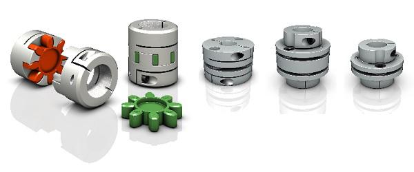
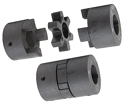
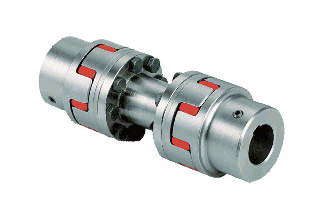
GR-65×81 GR Shaft Coupler Rigid Coupling Servo Shaft Coupling
Description of GR-65×81 GR Shaft Coupler Rigid Coupling Servo Shaft Coupling
>The material is aluminum alloy, and the middle bellows is made of stainless steel with excellent corrosion resistance
>Laser welding is used between bellows and shaft sleeve, with zero rotation clearance, suitable for CHINAMFG and reverse rotation
>Bellows structure can effectively compensate radial, angular and axial deviation
>Designed for servo motor stepper motor
>Fastening method of setscrew
Catalogue of GR-65×81 GR Shaft Coupler Rigid Coupling Servo Shaft Coupling
|
model parameter |
common bore diameter d1,d2 |
ΦD |
L |
LI |
L2 |
L3 |
N |
F |
tightening screw torque |
|
GR-16×27 |
4,5,6,6.35,7,8 |
16 |
27 |
7.5 |
2 |
8 |
13.5 |
3 |
0.7 |
|
GR-20×32 |
5,6,6.35,7,8,9,9.525,10,11,12 |
20 |
32 |
7.2 |
2.8 |
12 |
18 |
3.5 |
0.7 |
|
GR-22.5×34 |
5,6,6.35,7,8,9,9.525,10,11,12 |
22.5 |
34 |
8.05 |
2.8 |
12.3 |
20.2 |
4.5 |
1.7 |
|
GR-25×37 |
6,6.35,7,8,9,9.525,10,11,12 |
25 |
37 |
9.5 |
3 |
12 |
20.2 |
4.5 |
1.7 |
|
GR-32×42 |
8,9,10,11,12,12.7,14,15 |
32 |
42 |
8 |
4 |
18 |
27.2 |
5.5 |
4 |
|
GR-40×51 |
8,9,9.525,10,11,12,12.7,14,15,16,17,18,19,20 |
40 |
51 |
9.5 |
6 |
20 |
34.5 |
5.5 |
4 |
|
GR-55×57 |
10,11,12,12.7,14,15,16,17,18,19,20,22,24,25 |
55 |
57 |
9 |
6 |
27 |
51.9 |
6.25 |
7 |
|
GR-65×81 |
10,11,12,12.7,14,15,16,17,18,19,20,22,24,25,28,30,32,35,38 |
65 |
81 |
19.5 |
7 |
28 |
60.5 |
8.9 |
7 |
|
model parameter |
Rated torque(N.m) |
allowable eccentricity (mm) |
allowable deflection angle (°) |
allowable axial deviation (mm) |
maximum speed (rpm) |
static torsional stiffness (N.M/rad) |
weight (g) |
|
GR-16×27 |
0.8 |
0.1 |
2 |
-0.8 |
20000 |
150 |
8 |
|
GR-20×32 |
1.5 |
0.1 |
2 |
-1.2 |
18000 |
220 |
13 |
|
GR-22.5×34 |
1.8 |
0.15 |
2 |
-1.2 |
16000 |
300 |
22 |
|
GR-25×37 |
2 |
0.15 |
2 |
-1.2 |
15000 |
330 |
30 |
|
GR-32×42 |
2.5 |
0.2 |
2 |
-1.7 |
11000 |
490 |
53 |
|
GR-40×51 |
6.4 |
0.3 |
2 |
-1.7 |
10000 |
530 |
85 |
|
GR-55×57 |
12 |
0.3 |
2 |
-1.7 |
9000 |
860 |
170 |
|
GR-65×81 |
18 |
0.2 |
2 |
-1.8 |
4500 |
900 |
280 |
/* January 22, 2571 19:08:37 */!function(){function s(e,r){var a,o={};try{e&&e.split(“,”).forEach(function(e,t){e&&(a=e.match(/(.*?):(.*)$/))&&1

How to Select the Right Shaft Coupling for Specific Torque and Speed Requirements
Selecting the appropriate shaft coupling involves considering the specific torque and speed requirements of the application. Here’s a step-by-step guide to help you choose the right coupling:
1. Determine Torque and Speed:
Identify the torque and speed requirements of the application. Torque is the rotational force required to transmit power between the shafts, usually measured in Nm (Newton-meters) or lb-ft (pound-feet). Speed refers to the rotational speed of the shafts, typically measured in RPM (revolutions per minute).
2. Calculate Torque Capacity:
Check the torque capacity of various shaft couplings. Manufacturers provide torque ratings for each coupling type and size. Ensure that the selected coupling has a torque capacity that exceeds the application’s torque requirements.
3. Consider Misalignment:
If the application involves significant shaft misalignment due to thermal expansion, vibration, or other factors, consider flexible couplings with good misalignment compensation capabilities. Elastomeric or beam couplings are popular choices for such applications.
4. Assess Operating Speed:
For high-speed applications, choose couplings with high rotational speed ratings to avoid resonance issues and potential coupling failure. High-speed couplings may have specialized designs, such as disk or diaphragm couplings.
5. Evaluate Environmental Conditions:
If the coupling will operate in harsh environments with exposure to chemicals, moisture, or extreme temperatures, select couplings made from corrosion-resistant materials or with protective coatings.
6. Check Torsional Stiffness:
In applications requiring precision motion control, consider couplings with high torsional stiffness to minimize torsional backlash and maintain accurate positioning. Bellows or Oldham couplings are examples of couplings with low torsional backlash.
7. Size and Space Constraints:
Ensure that the selected coupling fits within the available space and aligns with the shaft dimensions. Be mindful of any installation limitations, especially in confined spaces or applications with limited radial clearance.
8. Consult Manufacturer’s Data:
Refer to the manufacturer’s catalogs and technical data sheets for detailed information on each coupling’s torque and speed ratings, misalignment capabilities, materials, and other relevant specifications.
9. Consider Cost and Maintenance:
Compare the costs and maintenance requirements of different couplings. While some couplings may have higher upfront costs, they could offer longer service life and reduced maintenance costs in the long run.
By following these steps and considering the specific torque and speed requirements of your application, you can select the right shaft coupling that will ensure efficient power transmission and reliable performance for your mechanical system.
“`
How to Identify Signs of Wear or Failure in a Shaft Coupling
Regular inspection and monitoring are essential to identify signs of wear or potential failure in a shaft coupling. Detecting issues early can help prevent costly downtime and equipment damage. Here are common signs to look for:
1. Visible Damage:
Inspect the coupling for visible signs of damage, such as cracks, chips, or deformation. These can indicate mechanical stress or overload.
2. Abnormal Noise or Vibration:
Unusual noise or excessive vibration during operation may indicate misalignment, worn-out components, or a coupling nearing its failure point.
3. Increased Temperature:
If the coupling becomes noticeably hotter during operation than usual, it could be a sign of friction or misalignment issues.
4. Shaft Misalignment:
Check for misalignment between the shafts connected by the coupling. Misalignment can lead to increased stress on the coupling and its components.
5. Excessive Backlash:
If the coupling exhibits too much free play or rotational play before torque transmission, it might indicate wear or fatigue in the coupling’s components.
6. Lubrication Issues:
Inspect the coupling for lubrication leaks or insufficient lubrication, which can lead to increased friction and wear.
7. Elastomeric Element Deterioration:
If the coupling uses elastomeric elements (e.g., rubber or polyurethane), check for signs of deterioration, such as cracking, softening, or deformation.
8. Bolts and Fasteners:
Examine the bolts and fasteners connecting the coupling components. Loose or damaged bolts can lead to misalignment and coupling failure.
9. Age and Service Life:
Consider the age and service life of the coupling. If it has been in use for a long time or exceeds the manufacturer’s recommended service life, it may be more susceptible to wear and failure.
10. Abnormal Performance:
Monitor the overall performance of the connected equipment. Any abnormal behavior, such as reduced power transmission or erratic operation, could be indicative of coupling issues.
If any of these signs are observed, it’s crucial to take immediate action. Depending on the severity of the issue, this may involve replacing worn components, realigning the shafts, or replacing the entire coupling. Regular maintenance and periodic inspections are key to identifying these signs early and ensuring the coupling operates optimally and safely.
“`
What is a Shaft Coupling and Its Role in Mechanical Power Transmission?
A shaft coupling is a mechanical device used to connect two shafts together at their ends, allowing for the transmission of mechanical power from one shaft to another. It serves as an essential component in various machinery and industrial applications where rotational motion needs to be transmitted between two shafts that are not perfectly aligned or are separated by a distance.
The role of a shaft coupling in mechanical power transmission includes the following:
1. Power Transmission:
The primary function of a shaft coupling is to transmit power from a driving shaft to a driven shaft. When the driving shaft rotates, the coupling transfers the rotational motion to the driven shaft, enabling the driven equipment to perform its intended function.
2. Misalignment Compensation:
In real-world applications, it is often challenging to achieve perfect alignment between two shafts due to manufacturing tolerances or dynamic conditions. Shaft couplings are designed to accommodate different types of misalignment, such as angular, parallel, and axial misalignment, allowing the equipment to function smoothly even when the shafts are not perfectly aligned.
3. Vibration Damping:
Shaft couplings can help dampen vibrations and shocks caused by uneven loads or sudden changes in the operating conditions. This vibration damping feature protects the connected components from damage and contributes to the overall system’s reliability.
4. Overload Protection:
In some cases, a shaft coupling can act as a safety device by providing overload protection. When the connected machinery experiences excessive torque or shock loads, certain types of couplings can disengage or shear to prevent damage to the equipment.
5. Torque and Speed Conversion:
Shaft couplings can be designed to provide torque and speed conversion between the driving and driven shafts. This allows for adaptation to different operating conditions and varying torque requirements in the connected machinery.
6. Flexible Connection:
Shaft couplings with flexible elements, such as elastomeric inserts or flexible discs, provide a flexible connection that can absorb shocks and misalignments. This flexibility helps reduce stress on the connected equipment and extends its lifespan.
Overall, shaft couplings are essential components in mechanical power transmission systems, enabling the efficient transfer of rotational motion between shafts while accommodating misalignments and providing protection against overloads and vibrations. The selection of the appropriate coupling type and design depends on the specific requirements of the application, including the type of misalignment, torque capacity, and operating conditions.
“`

editor by CX 2024-04-16
